How Undersea Fiber Optic Cables Are Repaired: Deep-Sea ROVs, Cable Ships, and Global Internet Infrastructure
Undersea fiber cables carry 99% of global Internet traffic, relying on repair ships and deep-sea ROVs to maintain network continuity.

Submarine Fiber Optic Cables (2026): Deep-Sea ROV Utilities, Repair Fleets, and Infrastructure Resilience
Summary
Undersea fiber optic cables are the physical backbone of the global digital economy. The International Telecommunication Union [1] states that submarine cables carry roughly 99 percent of the world’s Internet traffic and international data exchange, while recent European policy documents describe a network of about 600 cable systems spanning up to 1.5 million kilometers on the seabed. Industry testimony to policymakers places the current in-service base at 596 systems, with a substantial announced pipeline still under development. [2]
The central analytical finding is that the relationship between undersea cable systems and deep-sea remotely operated vehicle capability is indispensable but asymmetric. ROVs are crucial for inspection, fault localization, post-lay burial, shallow-water repair support, and a growing share of survey and asset-management tasks. But they do not replace the core cable-ship-centered repair architecture, especially in ultra-deep water where initial recovery still often depends on grapnels, specialized ships, sterile jointing rooms, and robust surface logistics. In practice, ROV utility is highest at the margins that most influence outages and cost: nearshore burial, cable exposure verification, tooling, crossings, and post-repair reinstatement. [3]
A second finding is that the constraints now most likely to define system performance between 2026 and 2040 are less about optical physics than about resilience architecture: route diversity, landing-station hardening, repair-vessel availability, permitting speed, and security governance over wet-plant and dry-plant control points. The European Commission [4] has moved from general resilience language to explicit policy and funding measures aimed at cable repair capacity, while the Federal Communications Commission [5] has tightened national-security scrutiny over cable landing licenses, covered equipment, foreign control, and operational access at landing stations. [6]
A third finding is that industrial convergence is accelerating. Telecom cables, offshore wind power cables, environmental sensorized cables, remote inspection services, and coastal data-center interconnection are increasingly drawing on overlapping vessels, survey methods, fiber-sensing techniques, and ROV/AUV service models. That convergence creates economies of learning, but it also couples risk: the same scarce deepwater intervention ecosystem now matters simultaneously to connectivity, offshore energy, national security, and marine observation. [7]
Architecture and installation
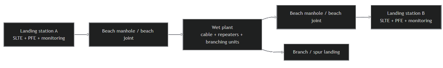
Modern submarine cable systems combine optical transmission, remote electrical powering, marine civil works, and terrestrial interconnection. The basic transoceanic design is a repeatered system: optical signals travel over multiple fiber pairs, are periodically amplified by subsea repeaters, can be split or routed by branching units, and terminate in landing stations that host Submarine Line Terminal Equipment, power feed equipment, and monitoring systems. Shorter systems can be repeaterless, especially for continent-to-island or island-to-island spans. [8]
The wet/dry distinction matters strategically as much as technically. The FCC’s definition is especially useful: the wet segment makes landfall at the beach manhole or beach joint and connects to the dry segment and the cable landing station; the landing station is the dry-land facility where traffic terminates into terrestrial networks, and where equipment such as SLTE and power-feed equipment may be concentrated. This means that “subsea resilience” is never purely subsea: it includes beach transitions, power grounding, backhaul to points of presence, and often nearby data-center infrastructure. [9]
The architecture also explains where costs and risks accumulate. Repeaters maintain long-haul optical performance and return supervisory signals that help operators diagnose section loss and repeater faults. Branching units split optical transmission and power-feed lines and, in some designs, remotely switch the power-feed path to minimize the impact of a fault. Power-feed equipment on shore supplies stable constant DC current, measures cable resistance under fault conditions and supports location search functions. These are not peripheral systems; they are operational control points. [10]
| System Element | Operational Role | Why It Matters for Resilience and Subsea Intervention |
|---|---|---|
| Fiber pairs | Capacity unit and commercial allocation unit | Determines commercial structure, restoration flexibility, and spare-pair strategy |
| Repeaters | Optical amplification and supervisory monitoring | Central to ultra-long-haul performance and fault diagnosis |
| Branching units | Optical and power split; path switching | Limits blast radius of faults and enables controlled reconfiguration |
| Landing station | Traffic termination into terrestrial networks | Security-sensitive dry-plant node and frequent concentration point |
| Power feed equipment | Remote DC powering and electrical fault support | Essential for repeatered systems and electrical diagnostics |
| Wet plant | Cable, repeaters, branching units, joints | Physically difficult to access and expensive to repair |
| Dry plant | Landing station, SLTE, power, backhaul | More physically accessible, but often the governance and cyber weak point |
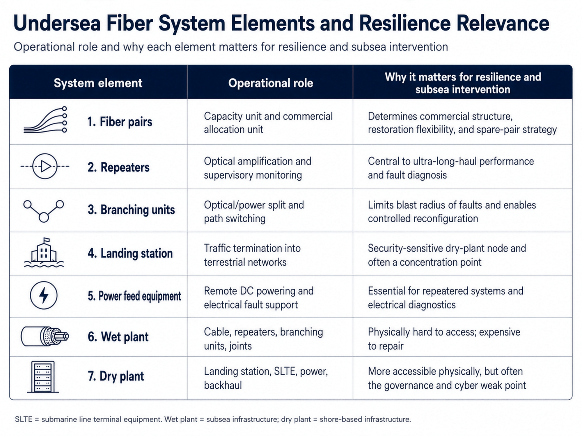
Sources for the table: FCC technical description and NEC technical papers. [11]
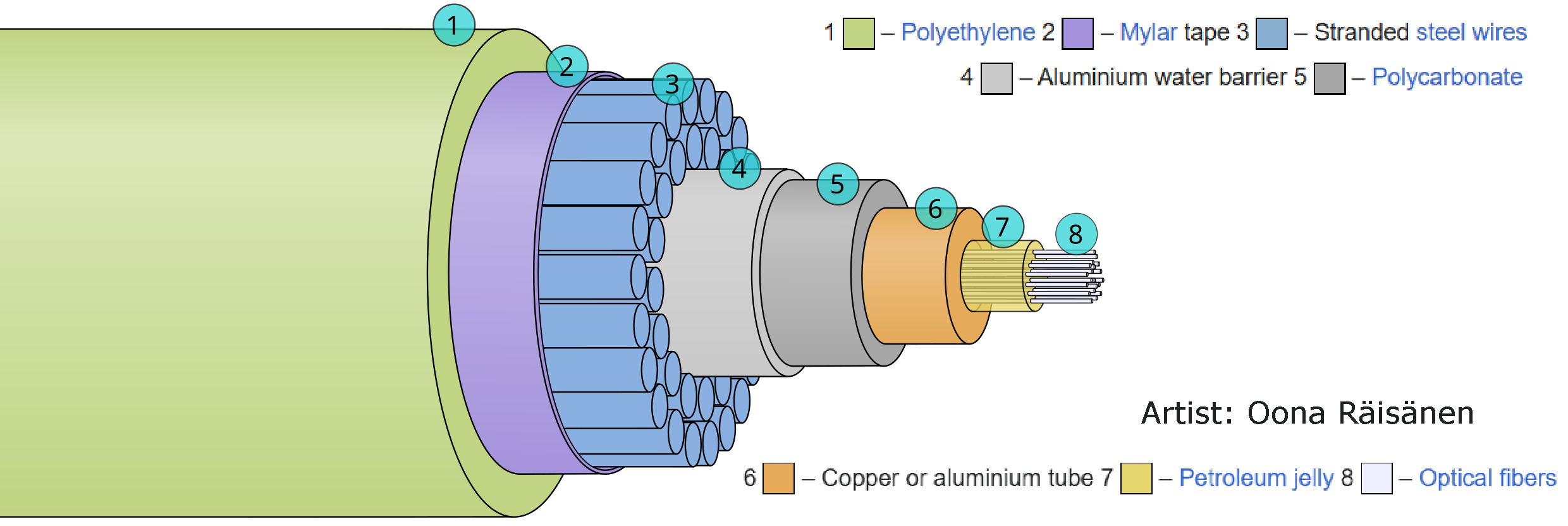
Protection strategy is depth- and threat-dependent. ITU guidance emphasizes that cables must be able to resist hydrostatic pressure, corrosion, abrasion, and marine-life exposure, while also being “adequately protected” by burying or armoring against trawlers and anchors. Near shore and other high-risk sections, additional protections can include rocky armor, single or double steel wire armoring, articulated pipe, and burial. In contemporary practice, burial is concentrated in aggression-prone shallow water rather than uniformly across abyssal plains. [12]
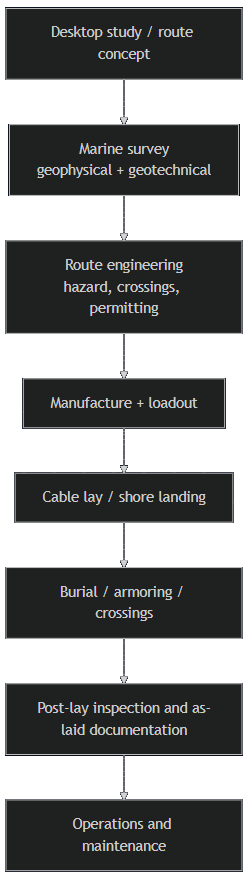
Installation is therefore an engineering sequence, not a single marine operation. A route begins with desk research and route selection, then moves into geophysical and geotechnical survey using multi-beam echo sounders and sub-bottom profiling, then into route position listing, manufacture, loadout, lay, burial/protection, and as-laid documentation. In the United States, public environmental documentation shows that route surveys, specialized vessels, burial equipment, coastal landing-station construction, and subsequent maintenance/repair all fall inside an interagency permitting framework that can involve the FCC, the U.S. Army Corps of Engineers, and National Oceanic and Atmospheric Administration [13] depending on the route. [14]
Cable-lay methods vary by seabed condition. Surface lay is fastest where threat analysis permits. Simultaneous lay-and-bury typically uses a towed plough and remains the preferred primary burial method where seabed conditions allow. Where ploughing is not feasible, surface lay can be followed by post-lay burial using trenching or jetting ROVs; this is generally slower, may require multiple passes, and works best in softer sediments. Pre-lay grapnel runs are used in some subsea-cable and offshore-cable projects to remove debris before installation. Those methods are most formally documented in power-cable guidance, but the operational logic is directly relevant to telecom wet-plant work. [15]
The resulting capex profile is heavily front-loaded. Public data on project-by-project cost disclosure are uneven, but the engineering evidence strongly supports an inference that the biggest cost drivers are route length, wet-plant complexity, number of landings and branches, nearshore protection requirements, survey intensity, and schedule risk from permitting. [16]
Deep Dive Into Undersea Fiber Optic Cabling and the Connection to Deep-Sea ROV Utilities
ROV and AUV utilities and limits
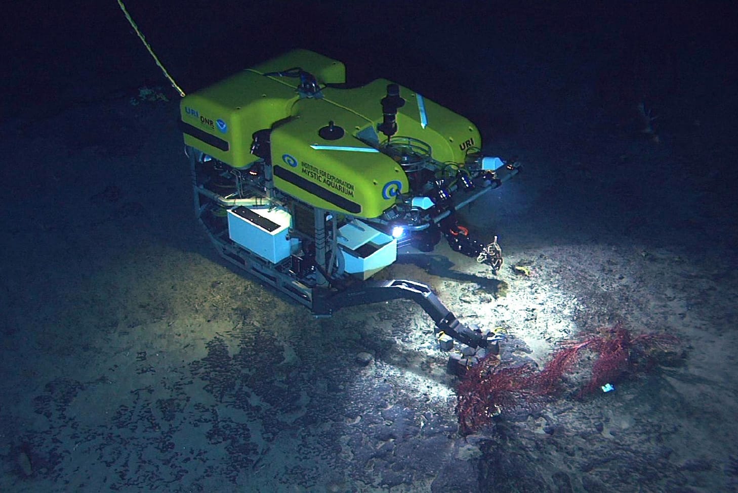
The cleanest functional distinction comes from NOAA: an AUV operates independently from the ship and has no connecting cable, while an ROV is tethered to operators on the ship. That difference drives almost every operational trade-off relevant to cable systems. AUVs are excellent for broad-area seabed survey, route corridor mapping, and lower-crewed data acquisition. ROVs are superior where the task requires live video, manipulation, cutting, burial support, or interaction with a specific asset. [17]
For telecom cables, the highest-value ROV uses fall into six categories. First, route and seabed verification: visual confirmation of features identified in geophysical survey, especially at crossings, steep slopes, or complex landfalls. Second, fault localization: confirming exposure, displacement, or damage in shallow or structurally complex areas such as beach approaches, manholes, or J-tube equivalents. Third, manipulation and tooling: cutting, attaching recovery lines, placing clamps, exposing cable, and supporting reburial. Fourth, trenching and post-lay burial: especially with jetting systems where ploughing is impractical. Fifth, post-repair inspection and burial assurance. Sixth, support to repair ships by reducing uncertainty before and after heavy-lift or grapnel phases. [18]
The limits are equally important. Most deep-ocean ROVs do not exceed 6,000 meters because cable design and communications constraints make greater depths harder and more expensive; NOAA’s Deep Discoverer is representative of the 6,000-meter class. More fundamentally, conventional tethered ROVs require a capable surface vessel, dynamic positioning, launch-and-recovery gear, expert pilots, and a tether that imposes drag, excursion limits, and entanglement risk near complex infrastructure. Academic reviews of underwater industrial inspection emphasize those constraints directly. [19]
Hybrid systems partially relax those limits but do not eliminate them. The Woods Hole Oceanographic Institution [20] has demonstrated hybrid concepts using microtethers and onboard batteries, allowing extended excursion from the ship with less maneuverability penalty than a heavy umbilical. That is highly relevant to cable and infrastructure inspection in cluttered or ice-affected environments. But hybrid systems remain battery-constrained, operationally specialized, and not yet a substitute for mainstream cable-maintenance methods at industrial scale. [21]
| Vehicle Class | Best Cable-Related Uses | Advantages | Core Limits |
|---|---|---|---|
| Observation-class ROV | Visual inspection, exposure checks, depth-of-burial support, shallow and intermediate surveys | Lower cost, smaller operational spread, fast deployment | Limited tooling and payload capacity; tether drag remains |
| Work-class ROV | Manipulation, cutting, attachment, jet trenching, post-repair burial | Heavy tooling, manipulators, sonar, precision intervention capability | Requires larger vessel, dynamic positioning (DP), and more crew support |
| AUV | Route engineering, multibeam mapping, repeated corridor surveys | Untethered range, smaller vessels, efficient area coverage | Limited real-time intervention and reduced manipulation capability |
| Hybrid ROV/AUV | Extended inspection in cluttered or ultra-remote conditions | Reduced umbilical burden, real-time control plus autonomy options | Battery-limited, niche operational envelopes, complex support model |
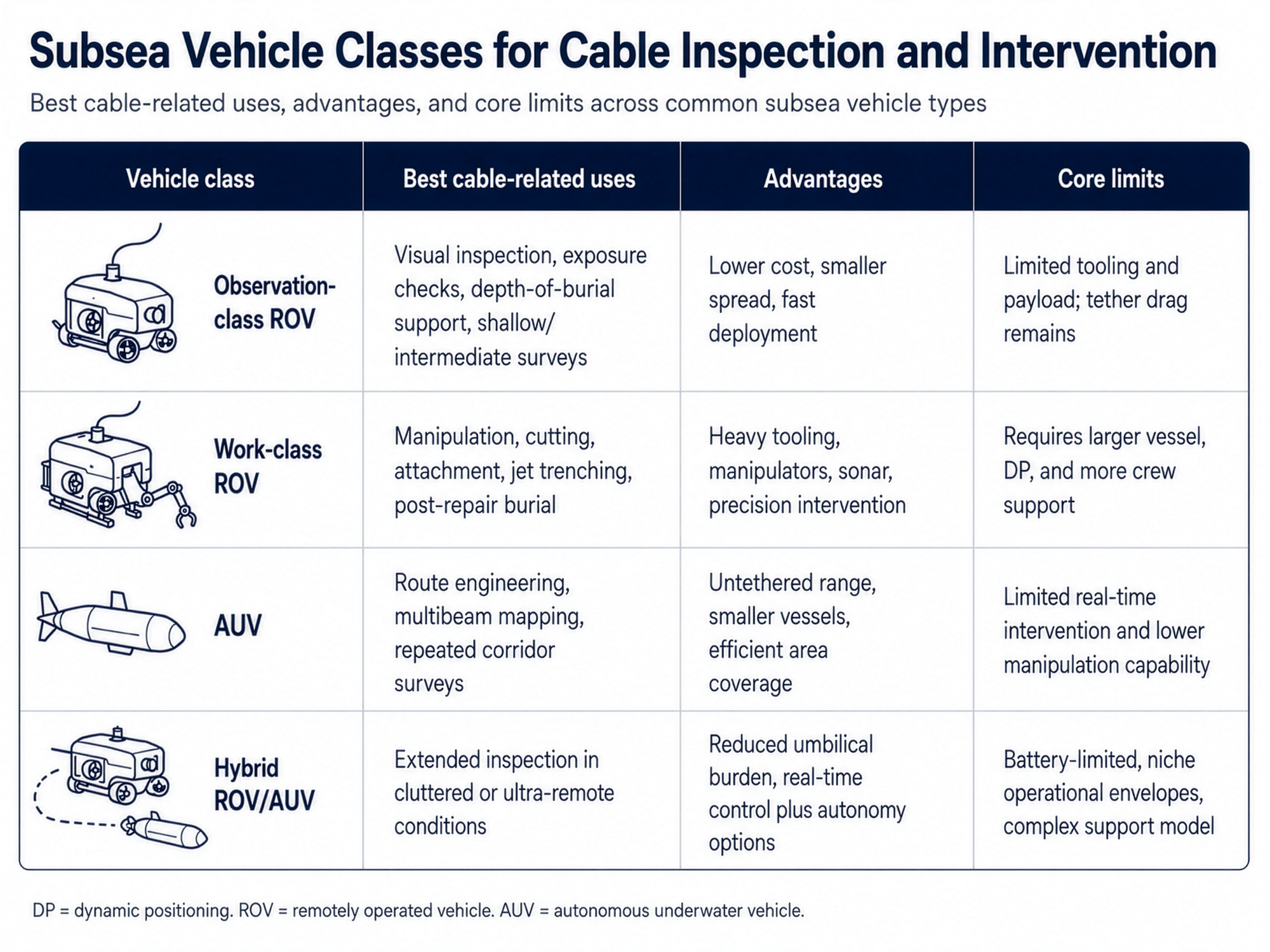
This table is a synthesis based on NOAA descriptions, subsea inspection literature, and vendor/operator materials. [22]
The practical implication is straightforward: ROV capability expands the intervention envelope but does not erase cable-system dependence on ships, weather windows, and surface control. In shallow water and at the shore end, ROVs can be decisive. In deep water, they are often complementary to grapnel recovery rather than a full substitute for it. [23]
Maintenance, failure modes, and repair lifecycle
The maintenance problem is structurally persistent. The International Cable Protection Committee [24] reports an average of roughly 150 to 200 faults globally each year, requiring about three repairs per week, and identifies accidental human activity, especially fishing and anchoring, as the dominant cause set. Historical ICPC data attributed 67 percent of faults to fishing and 8 percent to anchors; a 2024 presentation to the hydrographic community summarized fishing and anchoring risk as accounting for about 80 percent of cable faults. [25]
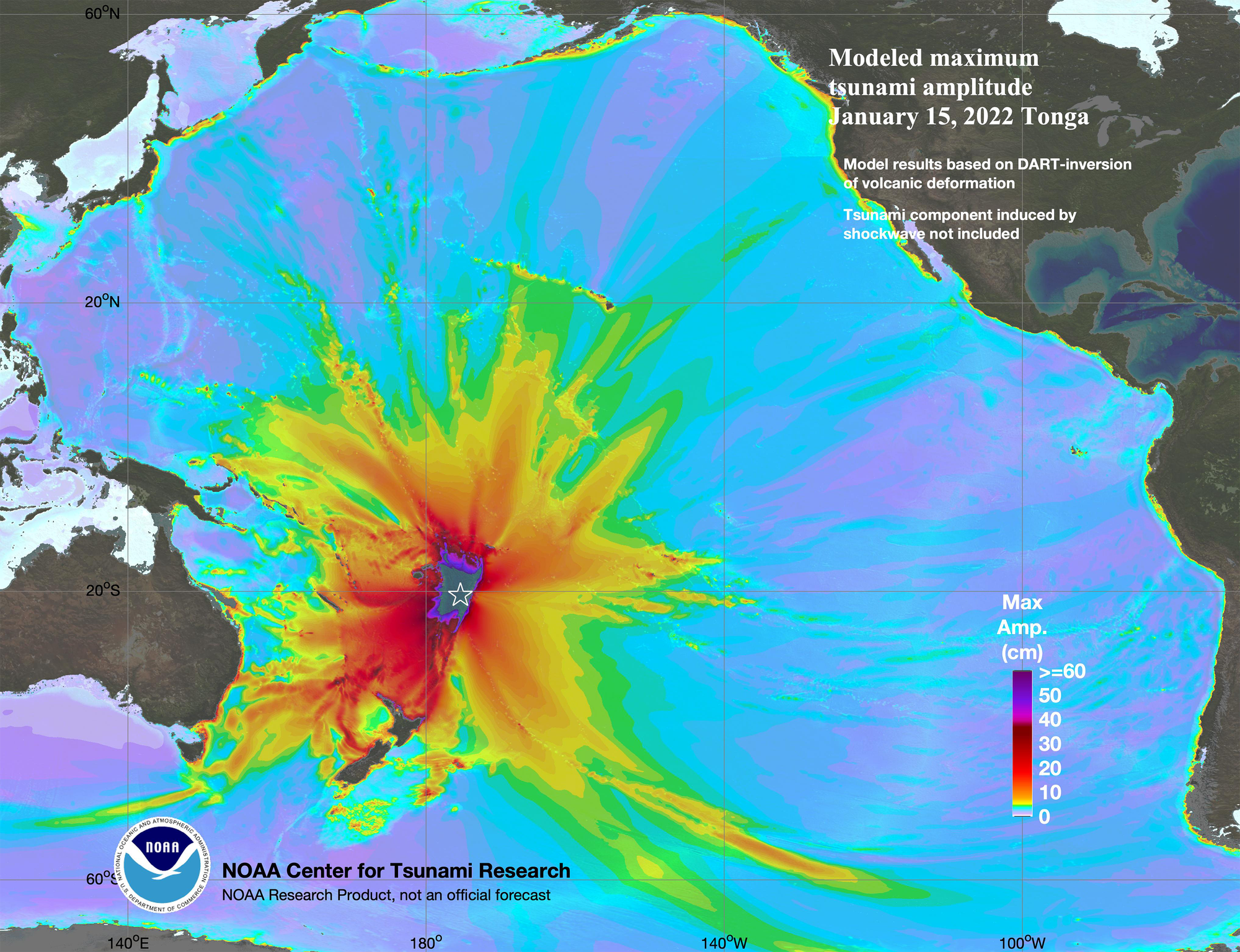
Natural hazards are less frequent but can be high-consequence. ICPC’s public environmental update states that natural hazards generally account for less than 5 percent of cable faults annually, but eruptive, seismic, or landslide-driven events can sever multiple systems and disconnect entire island states, as seen in the wake of the Hunga Tonga event. Academic reviews also underline cable vulnerability to storm surge, cyclones, earthquakes, submarine landslides, floods, volcanic eruptions, and ice scour. [26]
Failure modes are therefore best categorized by mechanism rather than by simple intent. The first category is ordinary maritime interaction: anchors, gear, dredging, and uncharted seabed use. The second is geophysical hazard: slope failure, turbidity currents, earthquakes, volcanic mass flows, and coastal inundation. The third is latent technical failure: manufacturing defects, joint weakness, repeater failure, or installation error. The fourth is hostile or coercive disruption: sabotage, exploitation of landing-station concentration, or manipulation of management/control dependencies. Current policy attention is moving rapidly toward this fourth category even though the first category remains statistically dominant. [27]
Repair remains a specialized, multi-stage operation. Land-based tests first estimate the fault location. Permits must then be secured. The repair vessel transits to site, often uses a grapnel to locate and lift the cable, cuts and recovers ends if necessary, splices in spare cable aboard ship in a controlled jointing room, tests the restored section, and relays it to the seabed. If the fault is in a shallow buried section, an ROV may then re-bury the cable using water jets. KDDI’s public repair sequence notes that deep recoveries can take more than a day from 8,000 meters even after the cable end is caught. [28]

| Repair Stage | Primary Activity | What Usually Governs Duration |
|---|---|---|
| Fault detection and localization | Electrical and optical testing from shore | Network visibility and diagnostics quality |
| Permit and vessel mobilization | Authorizations, maintenance-zone dispatch, spare preparation | Jurisdiction, crisis conditions, administrative speed |
| Transit and weather window | Vessel reaches site and holds position | Distance, vessel availability, and sea state |
| Recovery and jointing | Grapneling, lift, cut, splice, test | Water depth, seabed condition, and fault complexity |
| Reinstatement | Relay, re-bury, verify | Burial requirement and ROV/tooling availability |
| End-to-end restoration | Network returned to normal routing | Route redundancy and whether multiple systems are affected |
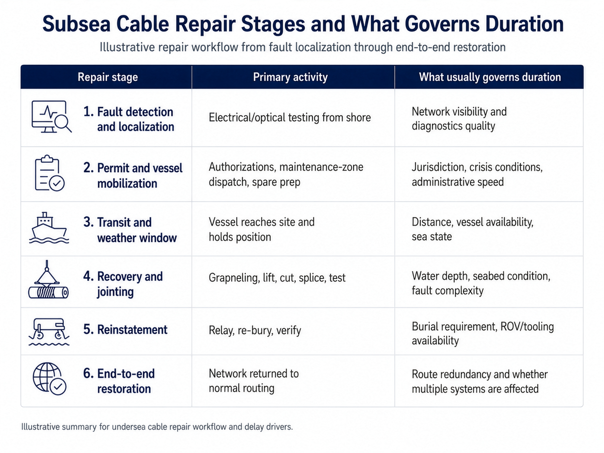
Indicative timing is multi-day under favorable conditions, but can extend to many weeks where permits, conflict, weather, or fleet scarcity intervene. [29]
This is where economics and operations converge. Public industry testimony says new submarine-cable investment has averaged above $2 billion annually over the last nine years and projects more than $14 billion worth of new systems entering service from 2025 to 2027, yet the maintenance fleet is aging and undercapitalized. TeleGeography [30] estimates that roughly 65 percent of maintenance vessels will reach end-of-life within 15 years. In other words, network kilometers are growing faster than the intervention base that must protect them. [31]
That imbalance has direct insurance and restoration implications. Direct physical repair cost is only one component; rerouting, latency degradation, prolonged business interruption, and backhaul overloads can dominate the economic impact. Public policy literature does not give a single universal insurance benchmark, but both national-security and maintenance analyses indicate that restoration costs can materially exceed the physical patch itself where route concentration is high or permits are delayed. [32]
Security, geopolitics, economics, and industrial convergence
Security policy has shifted from abstract concern to active regulation. The European Commission’s 2026 Joint Communication treats submarine communications cables and submarine electricity cables as linked critical infrastructure subject to hybrid campaigns. Its 2026 repair-capacity call explicitly cites deliberate disruption risk, especially after Baltic incidents, and frames repair capability itself as a resilience asset. In parallel, the FCC’s 2025–2026 rulemakings target foreign-adversary control, covered equipment, physical access, and certain IRU or capacity-lease arrangements that would give a foreign-controlled entity operational leverage over U.S. landing points and SLTE. [33]
The geopolitical problem is not simply “cables can be cut.” It is that connectivity is often concentrated in a limited number of corridors, landings, and governance chokepoints. Contemporary network design is improving route diversity, but it is uneven. TeleGeography’s 2025 workshop materials show growing geographic dispersion of trans-Atlantic and north trans-Pacific landings, but also emphasize that diversity of corridors matters more than merely adding more cables on a single corridor. Used capacity can still be highly concentrated even where map connectivity looks broad. [34]
The market structure has changed accordingly. TeleGeography’s evidence to policymakers found that content providers use a large majority of global international telecom capacity and that new investment has shifted sharply toward private or hyperscaler-backed cables. Its 2025 workshop slides show that building major new systems without hyperscaler involvement is becoming harder, although carriers remain important partners in more regulated markets and as buyers/swappers of spare fiber pairs. [35]
The named firms in this shift are no longer just telecom operators. Google [36] has continued to add new diverse paths and explicitly links them to resilience, cloud reach, and AI infrastructure. Meta [37], Microsoft [38], and Amazon Web Services [39] have all participated in major cable builds or private-capacity strategies. The strategic result is that cable ownership now sits closer to cloud, platform, and AI-service demand than in earlier consortium-dominated eras. [40]
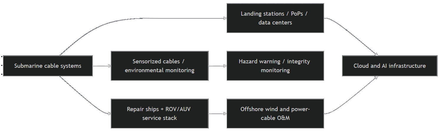
Industrial convergence is now one of the most consequential trends. The same offshore ecosystem increasingly supports telecom cables, offshore wind export and inter-array cables, seabed sensors, uncrewed inspection, and even experimental seabed-adjacent compute deployment. NEC [41] is using fiber-sensing techniques to monitor offshore wind power cables for burial depth and disturbance, with AI used to separate environmental noise from abnormal events. Fugro [42] is already performing remote ROV inspections in offshore wind settings using USV/eROV combinations. KDDI Cableships & Subsea Engineering, a Japanese cable vessel operator, publicly markets both route design/repair localization and ROV-enabled burial after repair. [43]
That convergence also reaches land. Public cloud companies explicitly frame subsea investment as part of integrated data-center, edge, and AI network strategy, while FCC materials note that a data center can itself serve as a cable landing station or house a point of presence. The undersea cable is therefore not only a maritime asset; it is an extension of terrestrial cloud topology and increasingly of energy-security planning. [44]
Risk matrix
The matrix below is an analytical judgment, not a deterministic forecast. Probability and impact ratings synthesize the public evidence cited in this report.
| Risk | Type | Probability | Impact | Mitigation |
|---|---|---|---|---|
| Fishing and anchor interaction | Accidental / maritime | High | High | Burial in shallow water, charting, protection zones, AIS-based enforcement, route avoidance |
| Landing-station concentration | Geographic / physical security | Medium | High | Diverse landing geography, inland backhaul redundancy, hardening of beach and CLS assets |
| Repair-vessel scarcity and permit delay | Operational | Medium-High | High | Regional repair agreements, vessel renewal, pre-cleared permits, spare-stock prepositioning |
| Natural-hazard cluster on vulnerable margins | Geophysical | Low globally, high locally | Very High | Route engineering, hazard avoidance, sensorized cables, corridor diversity |
| Foreign-control or management-plane leverage | Geopolitical / cyber | Medium | High | Licensing scrutiny, vendor vetting, control-plane segmentation, covered-equipment restrictions |
| Concurrent disruptions in a crisis zone | Conflict / sabotage | Low-Medium | Very High | Multi-corridor routing, government-to-government repair access, naval monitoring |
| Manufacturing or installation defect | Technical | Low | Medium-High | Factory and sea trials, QA/QC, as-laid verification, conservative wet-plant design |
| ROV depth/tether constraint during intervention | Technical / operational | Medium | Medium-High | Better vessel-ROV pairing, hybrid vehicles, preplanned tooling, smart route documentation |
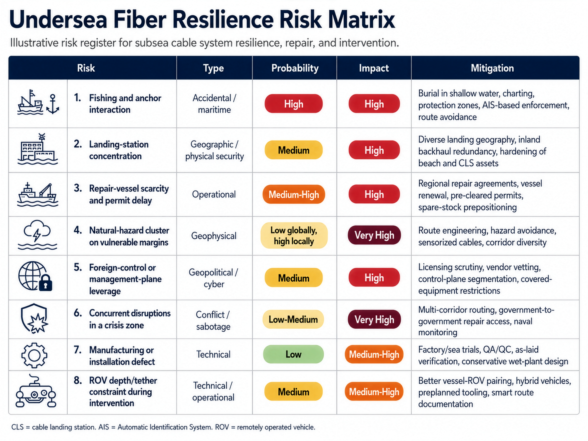
Supporting evidence: ICPC fault data and cause mix, EU repair-capacity policy, FCC security rules, ITU/ICPC resilience statements, and TeleGeography maintenance forecasts. [45]
Outlook 2026–2040
The near-term outlook is fact-based: more cable kilometers, more private-capital influence, and more security regulation. New investment remains strong, ownership is tilting toward private hyperscaler-backed builds, route diversity is being marketed as a resilience feature, and governments are moving from general awareness to repair-capacity and licensing actions. These are already visible facts, not forecasts. [46]
The medium-term outlook is best described as trend, not certainty. Between roughly 2030 and 2035, the strongest trend signals point toward more sensorized cables, wider use of optical-fiber condition monitoring on adjacent power-cable assets, and more remote or lightly crewed subsea inspection operations. The technical basis for cable-as-sensor applications is now well established in SMART-cable work and in offshore-wind monitoring trials; what remains uncertain is scale, cost allocation, and regulatory acceptance across jurisdictions. [47]
The long-term outlook to 2040 contains both robust trendlines and genuine speculation. A robust trendline is that route diversity, landing geography, and repair capacity will matter more, not less, as AI workloads deepen dependence on deterministic high-capacity connectivity. A plausible but still speculative outcome is partial autonomy in subsea maintenance: more hybrid vehicles, better onboard inference, and wider use of sensor-driven anomaly detection to narrow the search space before a manned intervention spread arrives. What is much less plausible, on current evidence, is a fully autonomous deep-ocean cable-repair paradigm that removes cable ships and surface logistics from the loop. The physics of lift, splice control, weather, and liability still favor supervised industrial operations. [48]
A second speculative but plausible development is wider convergence between telecom corridors and strategic energy corridors. The European Commission already treats communications cables and electricity cables as linked critical infrastructure, and offshore-wind monitoring work shows how communications fibers embedded in power cables can become a long-baseline sensing layer. If that model broadens, ROV firms and subsea integrators will increasingly sell into a combined connectivity-energy-monitoring market rather than into separate silos. [49]
Strategic implications and conclusion
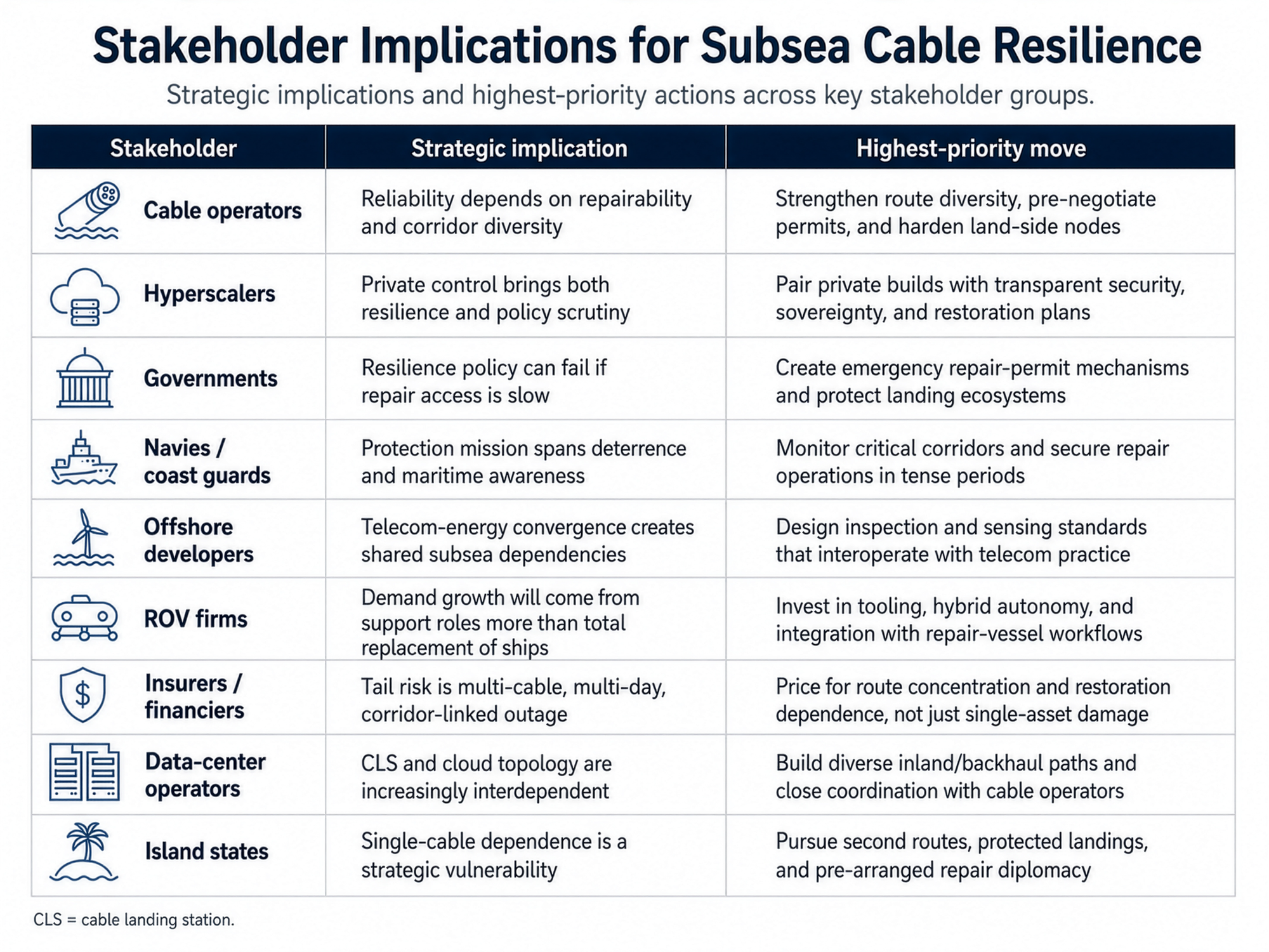
For operators, the priority is to stop treating resilience as a route-count metric and start treating it as a corridor-governance and repairability problem. For hyperscalers, the implication is that private ownership improves control but also raises sovereign-scrutiny and repair-governance exposure. For governments, the core issue is enabling fast lawful repair and securing landing-station ecosystems without overregulating deployment. For navies and coast guards, the mission is broader than deterrence against sabotage; it includes maritime-domain awareness around repair windows, anchor-drag behavior, and protection of crisis-time access for maintenance ships. For offshore developers and ROV firms, convergence means opportunity: the same inspection, burial, sensing, and repair-support capabilities will increasingly serve telecom, energy, and seabed-observation clients. For insurers and data-center operators, the key change is that business interruption and concentration risk may matter more than the physical cable break itself. For island states, the lesson is starkest of all: cable resilience is not a technical luxury but a continuity-of-state function. [50]
| Stakeholder | Strategic Implication | Highest-Priority Move |
|---|---|---|
| Cable operators | Reliability depends on repairability and corridor diversity | Strengthen route diversity, pre-negotiate permits, and harden land-side nodes |
| Hyperscalers | Private control brings both resilience and policy scrutiny | Pair private builds with transparent security, sovereignty, and restoration plans |
| Governments | Resilience policy can fail if repair access is slow | Create emergency repair-permit mechanisms and protect landing ecosystems |
| Navies / coast guards | Protection mission spans deterrence and maritime awareness | Monitor critical corridors and secure repair operations during tense periods |
| Offshore developers | Telecom-energy convergence creates shared subsea dependencies | Design inspection and sensing standards that interoperate with telecom practice |
| ROV firms | Demand growth will come from support roles more than total replacement of ships | Invest in tooling, hybrid autonomy, and integration with repair-vessel workflows |
| Insurers / financiers | Tail risk is multi-cable, multi-day, corridor-linked outage | Price for route concentration and restoration dependence, not just single-asset damage |
| Data-center operators | CLS and cloud topology are increasingly interdependent | Build diverse inland/backhaul paths and maintain close coordination with cable operators |
| Island states | Single-cable dependence is a strategic vulnerability | Pursue second routes, protected landings, and pre-arranged repair diplomacy |
The clear analytical judgment is this: the key consideration in undersea fiber optic cabling is no longer simply how to build ever-higher-capacity systems; it is how to build systems that can be found, protected, governed, and repaired under real-world maritime, political, and logistical stress. Deep-sea ROV utilities are central to that answer, but in a bounded way. They are force multipliers for survey, localization, burial, inspection, and selected interventions. They are not, today, the sovereign capability that determines whether the global cable system remains resilient. That sovereign capability lies in the full intervention stack: sound route engineering, hardened landings, shared legal frameworks, adequate repair fleets, and a subsea robotics ecosystem integrated with specialized ships rather than imagined as a substitute for them. [51]
Open questions / limitations. Publicly available evidence remains uneven on three issues: exact project-level capex and insurance pricing, the full scale of classified or unattributed hostile cable activity, and the pace at which SMART or sensorized-cable concepts will move from pilots to standard commercial deployment. Where this report discussed those subjects, it distinguished between observed facts, directional trends, and plausible but still speculative outcomes.
Citations
[1] [10] NEC Corporation. (2015). NEC Technical Journal: Submarine cable systems and technologies. https://www.nec.com/en/global/techrep/journal/g10/n01/pdf/100104.pdf
[2] [41] International Telecommunication Union. (2024). Submarine cable resilience. https://www.itu.int/en/mediacentre/backgrounders/Pages/submarine-cable-resilience.aspx
[3] [23] [28] [29] [31] [35] [38] [42] [46] Stronge, T. (2024). Written congressional testimony on submarine cable infrastructure. TeleGeography. https://blog.telegeography.com/hubfs/Tim%20Stronge%20Written%20Congressional%20Testimony%20%7C%20TeleGeography.pdf
[4] [14] [18] KDDI Cableships & Subsea Engineering Inc. (n.d.). Marine consulting services. https://www.k-kcs.co.jp/english/solution/marine_consulting.html
[5] [12] International Telecommunication Union. (2000). ITU-T Recommendation G.971: General features of optical submarine cable systems. https://www.itu.int/rec/dologin_pub.asp?id=T-REC-G.971-200004-S%21%21PDF-E&lang=e&type=items
[6] [7] [24] [33] [39] [49] European Commission. (2024). Joint communication to strengthen the security and resilience of submarine cables. https://digital-strategy.ec.europa.eu/en/factpages/joint-communication-strengthen-security-and-resilience-submarine-cables
[8] NEC Corporation. (2015). NEC Technical Journal: Optical submarine cable technologies. https://www.nec.com/en/global/techrep/journal/g10/n01/pdf/100102.pdf
[9] [11] [13] [20] [30] [44] U.S. Federal Register. (2025). Federal Register, Volume 90, Issue 48 (March 13, 2025). https://www.govinfo.gov/content/pkg/FR-2025-03-13/html/2025-03718.htm
[15] European Subsea Cables Association. (2018). Guideline 14: Power cable installation. https://www.escaeu.org/download/?Id=333
[16] [34] TeleGeography. (2025). PTC 2025 workshop presentation. https://www2.telegeography.com/hubfs/2025%20Content/Presentations/2025%20PTC%20Workshop.pdf
[17] [22] National Oceanic and Atmospheric Administration. (n.d.). What is the difference between an AUV and a ROV? https://oceanservice.noaa.gov/facts/auv-rov.html
[19] National Oceanic and Atmospheric Administration. (n.d.). How robots are uncovering the mysteries of the deep. https://oceanexplorer.noaa.gov/explainers/technology/
[21] Woods Hole Oceanographic Institution. (2009). Hybrid remotely operated vehicle Nereus reaches deepest part of the ocean. https://www.whoi.edu/press-room/news-release/hybrid-remotely-operated-vehicle-nereus-reaches-deepest-part-of-the-ocean/
[25] [36] [45] International Cable Protection Committee. (n.d.). International Cable Protection Committee (ICPC). https://www.iscpc.org/
[26] International Cable Protection Committee. (2023). Submarine cable protection and the environment. https://iscpc.org/publications/submarine-cable-protection-and-the-environment/ICPC_Public_EU_September_2023.pdf
[27] International Cable Protection Committee. (n.d.). Damage to submarine cables from dragged anchors. https://www.iscpc.org/publications/icpc-viewpoints/damage-to-submarine-cables-from-dragged-anchors/
[32] Center for Strategic and International Studies. (2024). Safeguarding subsea cables: Protecting cyber infrastructure amid great power competition. https://www.csis.org/analysis/safeguarding-subsea-cables-protecting-cyber-infrastructure-amid-great-power-competition
[37] [50] Center for Strategic and International Studies. (2024). Building cooperative frameworks for subsea cable security in the Indo-Pacific. https://www.csis.org/analysis/building-cooperative-frameworks-subsea-cable-security-indo-pacific
[40] Google Cloud. (2024). Announcing Sol transatlantic cable. https://cloud.google.com/blog/products/infrastructure/announcing-sol-transatlantic-cable
[43] NEC Corporation. (2024). Monitoring submarine power transmission cables with optical fiber sensing technology. https://www.nec.com/en/global/techrep/journal/g24/n01/240119.html
[47] Howe, B. M., et al. (2021). SMART subsea cables for observing the Earth and ocean, mitigating environmental hazards, and supporting the blue economy. Frontiers in Earth Science. https://www.frontiersin.org/journals/earth-science/articles/10.3389/feart.2021.775544/full
[48] Google Cloud. (2025). America-India Connect infrastructure connects four continents. https://cloud.google.com/blog/products/infrastructure/america-india-connect-infrastructure-connects-four-continents
[51] NEC Corporation. (2015). NEC Technical Journal: Advances in submarine cable systems. https://www.nec.com/en/global/techrep/journal/g10/n01/pdf/100111.pdf